Instruments and Gauges
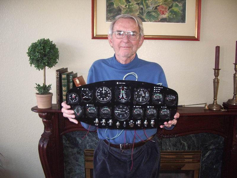
| Dad, after helping me mount all the gauges into the instrument panel. | |
| I spent 4 or 5 years working out the instruments, wiring diagrams and electrical details. I started with the RotorWay Exec standard wiring drawing. I incorporated the KISS turbine gauges and wiring instructions. I got my Private Pilot license so I would understand what instruments, gauges and avionics were needed and how I should lay out the panels. (It seemed like a good idea.) And finally, I started building the panels and wiring the helicopter.
| |
 |
All of the JetExec instruments and switches are located in the front console. I eliminated the overhead switch panel because I didn't want switches and labels that close to my head. This seemed to reduce the wiring required too. (Note: You can click on these pictures to view in higher resolution.) |
 |
Another view. The vertical card compass is not yet installed. I'd like to mount it on top of the instrument console, but need to move the helicopter out into the open to check deviation first. May have to mount the VCC on the windscreen instead. |
 |
Gauges, upper left to right are clock, fuel level, airspeed, dual tachometer, altimeter, main rotor transmission temp, OAT, and bottom left to right are dual fuel pressure (boost pump and turbine), turbine oil pressure, turbine EGT, VSI, turbine oil temp, Rotax transmission temp and tail rotor gear temp. Idiot lights (alarm LEDs) are located above gauges for low fuel level, low oil pressure, main rotor temp, main rotor chip, Rotax chip, turbine chip, tail rotor chip, alternator/hi/low voltage, and a master alarm LED when any of the former are lit. A green LED also indicates when the oil cooler fan is running. Switches left to right are: Turbine Stop/Fuel Pump Run, Starter/Main Batt to Governor, Start/Aux Batt to Governor, Alternator switch and voltage regulator circuit breaker, Main Batt contactor key switch, Strobe/Nav Lights, Oil Cooler Fan, and an Extra Circuit (cigarette lighter receptacle) power. |
 |
Beneath the main panel are the radio (XCOM VHF760), transponder (Micro Air T2000 not yet installed), Main/Aux Batt volt/ammeter and the Hobbs meter. Switches are: Instrument Power/Instrument Lights; Avionics Power; ELT Arm; Instrument Light Dimmer knob; Alarm LED Test; Alarm LED Dimmer; Red (map)/Cabin (door) Lights; and Cabin Air fan. The pilot cyclic has switches for radio push-to-talk and channel swap, and landing light. The copilot cyclic has just the radio PTT switch. |
 |
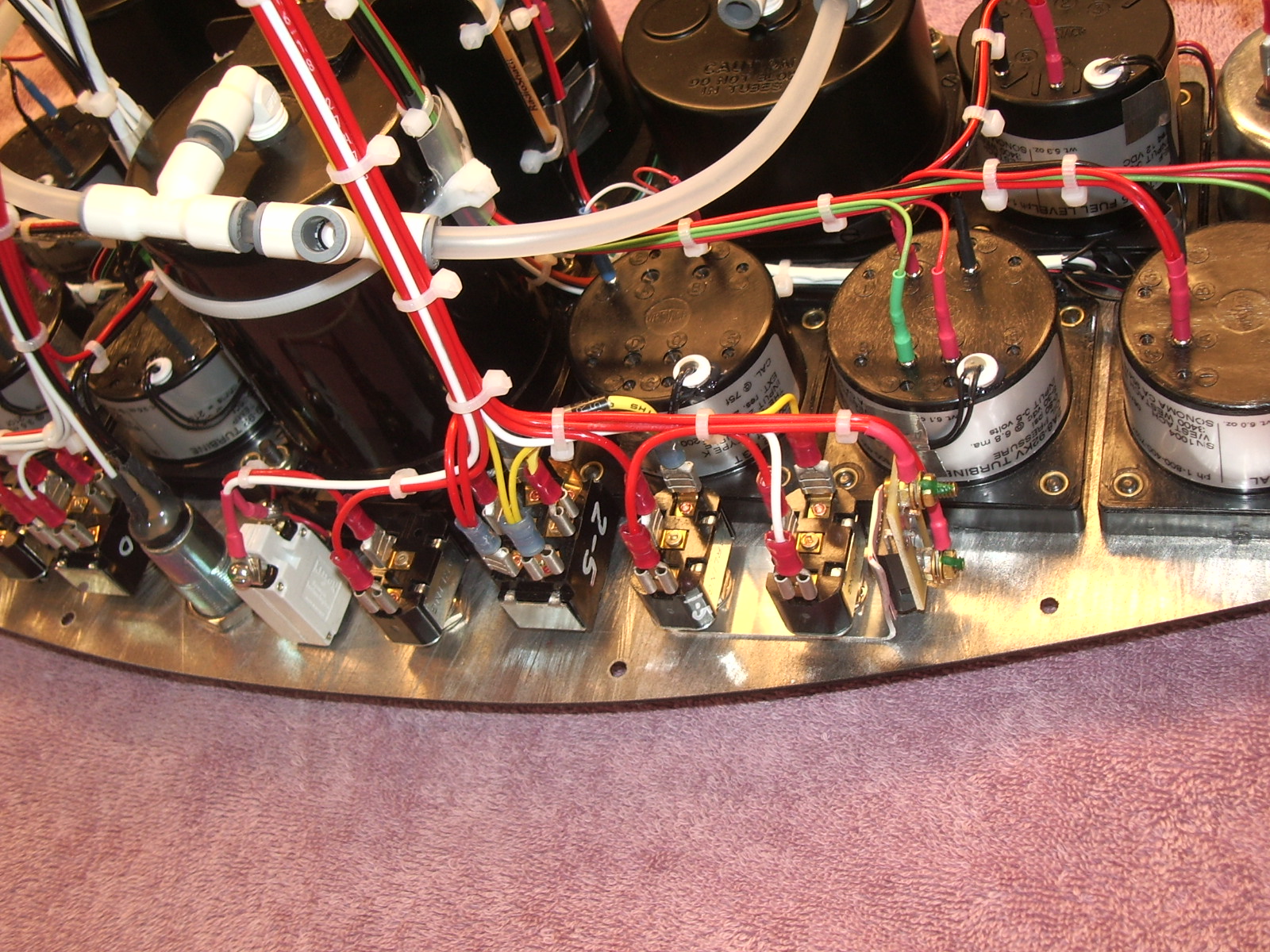
I wired the instrument and switch panels with Molex connectors for easy installation and removal. |
 |
Here is the main panel with alarm LED's wired (red and black wires) to the central LED board. The green and white wires are from four Nulite light ring bezels used to illuminate the 3-1/8" airspeed, dual tachometer, altimeter and VSI gauges. I bought internal lamp kits for all of the 2-1/4" Westach gauges. |
 |
Finished wiring and air connections, with a few more close-ups of the main panel: Instr10.jpg; Instr11.jpg; Instr12.jpg; and Instr13.jpg; and lower panel wiring Instr14.jpg and Instr15.jpg. |
| This pretty much wraps it up for the instrument panel and switches. The complete electrical system wiring is discussed in greater detail here. | |
Last Updated: October 26, 2012
| |