Frame Modifications for Turbine
| After suspending the turbine engine in the standard position over the frame, I grabbed a beer and got to thinking. Things started going downhill rapidly after that. In the standard KISS JetExec, the turbine is mounted with brackets directly on top of the Exec 162 frame. This is the simple, easy way, which does not require any frame modification other than welding the brackets to the frame. This does raise the C/G of the Exec slightly and it does make the helicopter somewhat less aerodynamic. Several builders have designed new "doghouse" cowlings that fit around the turbine and they do improve the flight characteristics of the JetExec.
Still, having the turbine sit up there just did not look right. I didn't like the higher C/G and I didn't like the fact that the standard Exec frame was not "properly" designed for the turbine. I realized that if the frame was just 2" wider, and if the KISS/Rotax C reduction gear was turned upward rather than down, that the turbine could be mounted about 5-1/2" lower, within the frame. I had another beer, started fondly fingering a red marking pen, and began to rationalize away any remaining vestige of common sense. The next day I placed a steel tubing order to Aircraft Spruce, and the hacksaw came out. | |
 |
This picture at left shows how the turbine is typically mounted. If you move your cursor over this text you can see the turbine lowered to its new position within the frame.
(Note: You can click on these pictures or the link above to view the picture in higher resolution.) |
 |
Here is the "before" photo with the engine in the standard position. |
 |
Here is the engine in its new position after the frame modifications. |
 |
These following pictures show some details of the frame modification. I bolted a piece of plywood to the back of the 1" square "drive" tubes to hold everything in position, then cut away the upper back half of the frame. The old frame tubes are laying on the floor at the bottom of the picture, along with some new pieces of 1" 4130 CrMo tubing that I heated and bent as replacement sections. |
 |
|
 |
Here are the replacement left and right 1" frame tubes welded in place, along with two new vertical support tubes. The new frame tubes are spaced approximately 2" wider than the original frame members. I heated the existing upper 1" diagonal tubes (near the M/R hood bracket) and bent them outward and slightly down to reconnect to the new frame tubes. The new left and right 1" frame tubes splice end to end with the original tubes at the point where they were previously welded to the lateral square drive tube. I used a 7/8" inner sleeve tube, then spliced and welded the 1" tube ends at a 45 degree oblique around the inner sleeve. |
 |
In this photo you can see where I replaced the previous 1" upper square drive tubes (both central and lateral) with new 1" square tubes. I shifted the new central square tube 4" to the right, and shifted the new lateral square tube approximately 3 or 4" rearward, closer to the turbine.
I also added a pair of L shaped mounting brackets for the base of the turbine gearbox. These are located on each side between the frame tubes and the lateral square tube. The last step was to replace or bend and re-weld the 1/2" diagonal support braces for the tail boom. |
 |
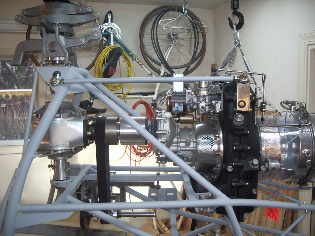
Here is the finished frame with the turbine installed in the new position. You can see the end of the jack-shaft, now located almost centerline beneath the turbine. The picture was taken from a perspective directly along the jack-shaft axis, slightly off A/C C/L. |
 |
|
 |
I used the original turbine mounting hardware to bolt the engine to the frame. The turbine gearbox had a pair of 2" x 3" x 1/4" steel plates with 1" dia mounting pins. I positioned the turbine gearbox between the L shaped mounting brackets mentioned above, aligned 1" dia holes in the brackets with the gearbox, then bolted the steel plates with the alignment pins through the L mounting brackets back onto the bottom of the gearbox. |
 |
The KISS kit came with one upper gearbox adjustable mounting rod. I built a second adjustable rod, and used the pair of them to attach the top of the turbine gearbox to the side plates on the M/R hood bracket. (Both rods can be seen in the pictures above and below.) |
 |
From this top view you can see that the new 1" square drive tube is offset to the right (upward in photo) of aircraft centerline. Because the input shaft for the new drive housing is 3/4" closer to aircraft centerline, this put the T/R drive belt too close to the center square drive tube. I repositioned the new square tube 4" to the right to move it further away from the belt, and to place the jack-shaft and T/R drive assembly closer to A/C C/L. |
 |
|
 |
|
 |
|
Last Updated: January 1, 2006
| |